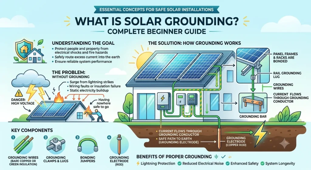
Solar grounding is the practice of connecting the metal parts of a solar power system to the earth, so that any stray or fault electrical current has a safe path to travel instead of flowing through a person or damaging equipment. Every solar installer knows this term. However, most homeowners hear it for the first time during a permit review or an inspection, and the jargon can feel intimidating.
I’ve spent over a decade inspecting, troubleshooting, and installing residential and commercial PV systems across the US. In that time, I’ve seen grounding done right, and I’ve seen it done dangerously wrong. This guide breaks down exactly what solar grounding means, why the National Electrical Code requires it, and what actually happens inside your system when it’s installed correctly.
Solar Grounding in Plain English
At its core, solar grounding does one job: it gives electricity an intentional, low-resistance path back to the earth if something goes wrong. Think of your solar array as a network of metal frames, racking rails, and enclosures. Under normal operation, none of that metal carries electrical current. However, if a wire frays, a connector corrodes, or insulation fails, that metal can become energized without warning.
Because of this risk, code requires every solar installer to bond all of those metal parts together and connect them to the ground. If a fault occurs, the current flows harmlessly into the earth instead of through a metal roof, a ladder, or a person’s hand. This is not a theoretical concern. I’ve personally traced shock complaints back to a single ungrounded junction box on more than one job site.
Grounding vs. Bonding: The Distinction Everyone Skips
Most articles use “grounding” and “bonding” interchangeably. That’s a mistake, and it’s the single biggest source of confusion I encounter when training new installers.
Bonding connects metal parts to each other so they sit at the same electrical potential. Picture every panel frame, rail segment, and enclosure on your roof wired together into one continuous metal network. Bonding alone doesn’t send current anywhere. It simply ensures nothing in that network can become energized relative to anything else nearby.
Grounding takes that bonded network and connects it to the earth itself, typically through your home’s existing grounding electrode system or a dedicated ground rod. This is where fault current actually goes when something fails.
In other words, bonding creates the safety network, and grounding gives that network somewhere to send a problem. A system can be perfectly bonded and still fail an inspection if the connection to earth is missing, corroded, or interrupted at a rail splice.
Why Solar Grounding Exists: The Three Real Reasons
Shock Protection
This is the reason most people already know. Without a grounding path, a single insulation failure can energize an entire metal roof or racking system. Anyone touching that metal, whether it’s a homeowner, a roofer, or a firefighter during an emergency, becomes the path to ground instead. Grounding removes that danger by giving the fault current somewhere else to go.
Fire Prevention
Ungrounded or poorly bonded systems allow fault current to arc rather than flow. Arcing generates intense, localized heat. In fact, DC arc faults are one of the leading causes of solar-related roof fires, which is exactly why NEC Article 690 pairs grounding requirements with arc-fault protection rules for rooftop systems.
System Performance and Code Compliance
Proper grounding also reduces electrical noise, which helps inverters and monitoring electronics run cleanly. Meanwhile, local Authorities Having Jurisdiction, or AHJs, will not issue Permission to Operate on a system with grounding deficiencies. I’ve watched installations sit unpowered for weeks over a single missed bonding jumper.
Where Solar Grounding Requirements Come From
In the United States, solar grounding is governed primarily by NEC Article 690, Part V, which covers PV-specific grounding and bonding. This section works alongside NEC Article 250, which supplies the general grounding rules that apply to all electrical systems, not just solar.
Article 690.43 specifically requires that exposed, non-current-carrying metal parts, including module frames, racking rails, and enclosures, connect to a continuous equipment grounding conductor. Article 690.47 then addresses how that conductor ties back into your home’s existing grounding electrode system.
Hardware standards matter just as much as the code itself. UL 2703 governs mounting and grounding devices used to secure and bond PV modules, which is why listed racking systems can now serve as the bonding path instead of requiring separate copper jumpers between every panel.
If any of this sounds abstract right now, don’t worry. In the next section, I’ll walk through the actual difference between equipment grounding and system grounding, and why most modern residential inverters are intentionally “ungrounded” without being unsafe.
Equipment Grounding vs. System Grounding: The Difference That Confuses Everyone
NEC Article 690 actually describes two separate types of grounding, and conflating them causes most of the confusion I see on job sites. Understanding both is the key to understanding why your neighbor’s 2010 solar system looks wired completely differently from a system installed today.
Equipment Grounding: Mandatory, No Exceptions
Equipment grounding bonds every non-current-carrying metal part, think panel frames, racking rails, junction boxes, and inverter enclosures, to earth through an Equipment Grounding Conductor, or EGC. This requirement applies to every residential and commercial PV system installed in the United States. There are no exceptions, and no installer or inspector can waive it.
The EGC exists purely for safety. It never carries current under normal operation. Its entire job is to stand ready, so that if a fault sends current into the metal frame of a panel, that current has a fast, low-resistance path back to the source instead of lingering in the hardware or seeking out a person.
System Grounding: Situational, Not Universal
System grounding is different. It connects one of the current-carrying conductors, typically the negative DC conductor, directly to earth. Unlike equipment grounding, system grounding is not required on every installation.
Older transformer-based inverters generally required system grounding under NEC 690.41(A). However, most inverters installed today are transformerless, and code prohibits system grounding on most of these designs. As a result, the large majority of residential rooftop systems installed since the early 2010s run as “ungrounded” systems from a system-grounding standpoint, even though every single one is still fully equipment-grounded.
This is exactly the distinction that trips up homeowners. I’ve had clients panic after reading online that their system is “ungrounded,” assuming it means unsafe. In reality, it usually means their transformerless inverter simply doesn’t use system grounding, while equipment grounding, the part that actually protects people, remains fully in place and mandatory.
Why the Industry Moved Toward Ungrounded Inverter Architecture
Transformerless inverters became the residential standard for a practical reason: efficiency. Removing the internal isolation transformer cuts weight, reduces cost, and improves conversion efficiency by a measurable percentage. Because these inverters isolate DC from AC electronically rather than through a physical transformer, system grounding becomes both unnecessary and, in most configurations, unsafe to add.
This shift didn’t happen overnight. It followed years of testing and standards development, most notably through UL 1741, which governs inverters, converters, and controllers used with distributed energy resources. Meanwhile, IEEE 1547-2018 established the broader interconnection standards that utilities now rely on when approving grid-tied systems.
Ground-Fault Protection: The Safety Net Behind Ungrounded Systems
Because ungrounded PV systems don’t have a single reference point tying the DC circuit to earth, they rely instead on Ground-Fault Protection Devices, or GFPDs, built into the inverter or a separate combiner box. These devices continuously monitor for unintended current leaking to ground. If they detect a fault, they interrupt the circuit automatically, often within milliseconds.
This is worth explaining plainly, because it addresses the exact fear I hear most often on site visits: “If my system is ungrounded, how does it stay safe?” The answer is that equipment grounding handles the physical safety path, while ground-fault detection handles the electronic monitoring layer. Both work together, and neither replaces the other.
A Real-World Example From the Field
A few years ago, I inspected a residential system where the homeowner’s neighbor, an electrician by trade but not solar-certified, insisted the array needed a separate grounding rod driven into the yard because “that’s how grounding works.” Unfortunately, this created a second, isolated grounding point that wasn’t bonded to the main service ground.
That mistake introduced a dangerous voltage difference between the array’s ground and the house’s ground during a lightning event nearby. The fix required removing the auxiliary rod entirely and routing the array’s EGC back to the home’s existing grounding electrode system, exactly as NEC 690.47 requires. This is one of the most common and costly mistakes I still see, and it’s covered in more depth in our full step-by-step solar grounding installation guide.
Quick Reference: Grounded vs. Ungrounded PV Systems
| Feature | Grounded System | Ungrounded System |
|---|---|---|
| Inverter type | Transformer-based | Transformerless |
| System grounding | Required (690.41A) | Prohibited in most cases |
| Equipment grounding | Always required | Always required |
| Fault detection | Ground-fault relay | GFPD / continuous monitoring |
| Common era | Pre-2010s installs | Standard since ~2012 |
Understanding this table matters more than memorizing code sections. If you only remember one thing from this section, remember that equipment grounding is universal and non-negotiable, while system grounding depends entirely on your inverter’s design.
Next, I’ll walk through the physical hardware, ground rods, WEEB washers, bonding jumpers, and UL-listed racking, that make equipment grounding actually work in the real.
The Physical Hardware: How Solar Grounding Actually Works on a Roof or in a Field
Section 3 of 5
Understanding the code is one thing. Actually seeing how a grounding path is built, wire by wire, connector by connector, is what separates a textbook explanation from real installation knowledge. Let me walk through the hardware exactly as I install and inspect it.
The Equipment Grounding Conductor (EGC)
The EGC is the backbone of the entire safety system. In most residential installs, this is a bare or green-insulated copper conductor, commonly sized at 6 AWG, though exact sizing depends on the overcurrent protection ahead of it per NEC Table 250.122. This conductor runs continuously from the array, through the racking, down through conduit, into the solar disconnect, through the inverter, and finally terminates at the grounding busbar in your home’s main service panel.
Continuity matters more than almost anything else in this chain. A single break, whether from a loose lug, a corroded splice, or a rail segment that isn’t properly bonded, defeats the entire purpose of the EGC. I’ve failed inspections over exactly one missed bonding jumper between two rail sections that otherwise looked flawless.
WEEB Washers and Bonding Lugs
Before UL 2703-listed racking became standard, installers bonded each panel frame individually using WEEB (Washer, Electrical, Equipment Bonding) washers. These small, star-shaped washers sit between the panel frame and the mounting rail. As you tighten the mounting bolt, the washer’s teeth bite through the panel’s anodized coating and make direct metal-to-metal contact.
This detail matters because aluminum panel frames are anodized for corrosion resistance, which unfortunately also makes them electrically non-conductive on the surface. Skipping the WEEB washer and relying on a standard bolt is one of the most common mistakes I encounter, because the system will power on and appear to work perfectly, right up until a fault occurs with no path to ground.
UL 2703-Listed Racking Systems
Modern racking systems solve the WEEB-washer problem at scale. Racking listed under UL 2703 is engineered and tested to serve as the bonding path itself, meaning the rail electrically connects every panel frame mounted to it without requiring individual jumpers. This single change has eliminated thousands of labor hours industry-wide and reduced one entire category of installer error.
However, this only works if every rail splice includes a certified bonding jumper. Mechanical rail connections alone don’t guarantee electrical continuity, especially once thermal expansion, corrosion, or vibration loosen the joint over years of outdoor exposure. If you’re comparing racking options for your own roof, our solar panel roof mounting systems guide covers which listed systems handle this reliably.
The Grounding Electrode System (GES)
Once the EGC reaches your home’s main service panel, it terminates at the grounding busbar, which connects to your home’s existing Grounding Electrode System. This typically includes a ground rod, a metal water pipe connection, or a concrete-encased electrode, depending on your home’s construction and local code.
For roof-mounted systems, you generally do not install a new, separate ground rod. Doing so without properly bonding it to the main house ground creates what installers call a ground loop, a dangerous voltage difference between two grounding points that can actually attract lightning damage rather than prevent it.
Ground-Mounted Arrays: A Different Set of Rules
Ground-mounted systems change this picture because the array sits physically separate from the house. In these cases, installers typically drive a dedicated grounding electrode, often an 8-foot copper-clad rod, near the array itself, then bond it back to the main service ground rather than leaving it isolated.
Because a ground-mounted array has no building around it, it behaves like an exposed lightning target in open terrain. As a result, surge protection becomes far more important for ground mounts than for most rooftop installations, which I’ll cover in detail in the next section.
A Field Scenario: What a Correct Installation Looks Like
On a typical rooftop job, my sequence looks like this. First, I install the racking and confirm every rail splice includes a bonding jumper. Second, I seat a WEEB washer under each panel’s mounting point, even on UL 2703 racking, as a redundant safety measure. Third, I run a continuous, un-spliced EGC from the array’s grounding lug down through weatherproof conduit into the solar disconnect.
From there, the conductor passes through the inverter’s grounding terminal and terminates at the main panel’s ground bus. Finally, I test the entire path with a continuity meter before the system ever powers on. That last step catches problems that a visual inspection alone will miss almost every time.
This hardware chain, EGC, WEEB washers or listed racking, and the grounding electrode system, forms the complete physical answer to “what is solar grounding.” Next, I’ll cover the mistakes that cause inspection failures, how lightning protection differs from standard grounding, and a full comparison table of grounding methods.

I am Ethan Brooks is an author dedicated to exploring sustainability, technology, and forward-thinking solutions. His writing highlights simple yet powerful ways to improve everyday life while protecting the planet. He believes knowledge can drive meaningful change. Discover more at ecopowersence.com.