Updated June 14, 2026 · 12 min read · Dr. Marcus Reed
To ground a solar power system safely, you need two separate paths: Equipment Grounding (EGC) bonds all metal frames and rails to prevent shock, and System Grounding (GEC) connects the circuit to earth. In 2026, the type of grounding required depends entirely on your inverter — transformerless inverters (used in most modern residential systems) prohibit DC system grounding under NEC 690.41(B), while transformer-based inverters require it under NEC 690.41(A).
| Component | Function | Wire Gauge | 2026 NEC Reference |
| Equipment Grounding (EGC) | Bonds metal frames and rails | 10-12 AWG copper | NEC 690.43 |
| System Grounding (GEC) | Connects circuit to earth | 6 AWG bare copper | NEC 690.47 / 250 |
| Surge Arrestor (SPD) | Shunts lightning surges to ground | Pre-integrated or 10 AWG | NFPA 780 |
| Grounding Rod | Physical earth connection | 8ft x 5/8″ copper-clad steel | NEC 250.52(A)(5) |
Introduction
Learning how to ground a solar power system safely is the most critical safety step in any residential or off-grid solar installation. Get it right, and you have a low-resistance path that silently routes fault currents, static buildup, and surge energy into the earth — protecting your inverter, your battery bank, and anyone who touches the system. Get it wrong, and you face failed inspections, voided warranties, fire risk, and a lethal shock hazard.
In my decade of inspecting arrays across the U.S., the most common failure I see isn’t a cracked panel or a failing inverter — it’s an installer who misunderstood which type of grounding their specific inverter requires, or who skipped the anodized-coating step on aluminum rails. This guide covers both, along with the 2026 NEC code updates that are now failing permits across multiple states.
Why You Must Ground a Solar Power System Safely
When you ground a solar power system safely, you create a dedicated low-resistance path for stray electricity to travel into the earth — not through your body, your appliances, or your electronics.
Modern high-efficiency panels in 2026 generate significantly higher DC voltages than the panels common a decade ago, making the risk of arc-over and static buildup more severe. Without proper grounding, a lightning strike several hundred feet away can induce a voltage spike that destroys your entire battery bank. A local fault — a chafed wire touching a panel frame — can energize every metal surface on your roof.
We follow NEC Article 690 (solar PV systems) alongside NEC Article 250 (general grounding and bonding) to ensure every metal component is electrically continuous and safely discharged to earth.
People Also Ask
Q: Does a solar system need a dedicated grounding rod? A: Yes. While the solar grounding rod must be bonded to your home’s existing Grounding Electrode System (GES), solar arrays often require their own electrode to handle atmospheric surges. See NEC 690.47 for the specific bonding requirements.
EGC vs GEC: The Critical Difference (And Why Mixing Them Up Fails Inspections)
Equipment Grounding (EGC) bonds the metal parts of the system to prevent shock. System Grounding (GEC) connects the electrical circuit itself to the earth. Both serve different purposes — and in 2026, which one you install depends on your inverter type.
This is where most DIYers and even some installers make a costly error.
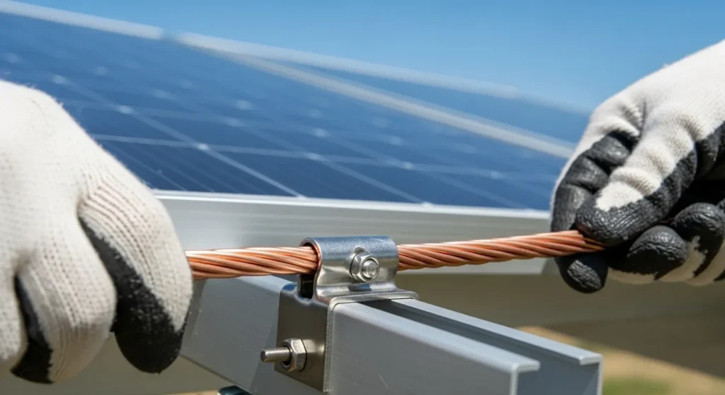
Equipment Grounding (EGC) — NEC 690.43 — involves bonding all non-current-carrying metal parts: panel frames, aluminum racking, inverter chassis, conduit, and enclosures. You must use UL-listed grounding lugs that penetrate the anodized coating on aluminum rails to reach bare conductive metal. If you don’t break that oxide layer, the ground path doesn’t exist, regardless of how the connection looks visually.
System Grounding (GEC) — NEC 690.41 — is where 2026 brings a critical distinction most older guides miss entirely:
- Transformer-based inverters (NEC 690.41(A)): System grounding is required — the DC negative must be bonded to earth.
- Transformerless inverters (NEC 690.41(B)): System grounding is prohibited at the DC level — these inverters use internal Ground Fault Protection (GFP) instead. Adding a DC system ground to a transformerless inverter is one of the leading causes of inspection failure and equipment damage in 2026.
The physical GEC connection to the grounding rod (6 AWG copper, bonded to your main service panel) remains required in both cases — only the DC circuit grounding changes.
People Also Ask
Q: Can I use the solar rail as the ground conductor? A: Yes, if the rails are listed under UL 2703 for grounding and bonding continuity across the array. Unlisted rails used as the EGC path is a common NEC 690.43 inspection failure.
NEC 690 Rapid Shutdown: The 2026 Requirement Most DIYers Miss
Before running a single grounding wire, understand NEC 690.12 — the rapid shutdown requirement. This is separate from grounding but directly related to inspection compliance, and it is the source of a significant percentage of solar permit rejections in 2026.
NEC 690.12 requires: controlled conductors within 1 foot of the PV array must reduce to 80 volts or less within 30 seconds of initiating a shutdown. Conductors outside that boundary must reduce to 30 volts or less within 30 seconds.
In practice, this means your inverter and any module-level power electronics (MLPEs) must be listed and certified to work together as a complete rapid shutdown system — not just individual compliant components paired at random. Inspectors test this functionality on-site. An incompatible inverter-optimizer pairing fails the inspection even if every grounding wire is perfect.
Why this matters for grounding: Many installers assume that if their grounding is solid, the inspection will pass. In 2026, rapid shutdown labeling and functionality are inspected at the same time as grounding continuity — a failure on either point stops the whole inspection.
How to Ground a Solar Power System Safely: Step-by-Step
Step 1: Check inverter type transformer-based or transformerless as it determines DC grounding rules under NEC 690.41.
: Bond all panel frames and rails using UL-listed lugs or WEEB washers per NEC 690.43.
: Run 10–12 AWG copper EGC alongside PV conductors to the inverter or combiner grounding busbar.
: Drive an 8-foot copper-clad rod vertically. Add a second rod if soil resistance exceeds 25 ohms.
Step 5: Connect 6 AWG bare copper GEC from inverter busbar to ground rod and bond to your home’s GES per NEC 690.47.
Step 6: Test with a multimeter. Near-zero resistance between farthest panel and ground rod confirms a solid connection.
Choosing the Right Components for 2026 Compliance
Grounding lugs: Must be UL-listed specifically for solar bonding — generic hardware does not provide the “teeth” needed to penetrate aluminum oxide coating. Look for UL 467 listing.
Grounding rod: 8-foot copper-clad steel rod, minimum 5/8-inch diameter (NEC 250.52(A)(5)). In coastal environments, use solid copper rods — salt spray corrodes the copper cladding on steel rods within a few years.
Wire: Use bare copper for underground and rod connections. Use THHN/THWN-2 jacketed copper for roof runs exposed to UV. Never use aluminum for the GEC — NEC explicitly prohibits aluminum grounding electrode conductors for PV systems, regardless of whether the lugs are AL/CU rated.
Fasteners: Use 316-grade stainless steel hardware for any coastal or high-humidity installation. Zinc-plated screws react with copper and create high-resistance oxidation over time — effectively breaking the ground path while appearing visually intact.
Anti-oxidant compound: Apply Noalox or equivalent anti-oxidant joint compound to all copper-to-aluminum connections to prevent galvanic corrosion from slowly increasing contact resistance over years.
For verified component listings, theUL Product iQ database allows you to confirm whether specific lugs, clamps, and rods are listed for their intended solar grounding application.
People Also Ask
Q: Is bare copper wire better than insulated for grounding? A: Bare copper is required for the direct connection to the grounding rod buried in earth. Insulated (THHN/THWN-2) copper is preferred for roof runs and conduit to prevent accidental shorts and UV degradation.
Lightning Protection and Surge Suppression: What Grounding Can and Cannot Do
Solid grounding is necessary for lightning protection, but it is not sufficient on its own. Understanding the distinction prevents a dangerous misunderstanding that costs homeowners thousands in destroyed equipment.
Your 6 AWG grounding wire handles fault currents at 120-600V and bleeds off static charge from wind moving across the panels. A direct lightning strike carries upwards of 300 million volts and 30,000 amps — a 6 AWG copper wire will vaporize in milliseconds under that load.
What actually protects your system from lightning and surge damage is a Surge Protective Device (SPD). Install Type 2 SPDs on both the DC input (between panels and inverter) and the AC output (between inverter and main service panel). SPDs contain Metal Oxide Varistors (MOVs) that instantaneously shunt the surge to your ground path, bypassing sensitive electronics.
Important: lightning protection under NFPA 780 is a separate system from NEC equipment grounding. NEC does not require NFPA 780 lightning protection for PV systems, but your local Authority Having Jurisdiction (AHJ) or insurance carrier may require it in high-lightning-risk areas. Check before you build.
For detailed standards, theIEEE lightning protection guidelines andNFPA 780 are the authoritative references.
People Also Ask
Q: Can solar panels survive a direct lightning strike? A: Rarely — a direct strike carries far more energy than any grounding wire can handle. However, a properly grounded system with SPDs on both DC and AC sides prevents the surge from destroying your inverter, batteries, and interior appliances.
Off-Grid vs Grid-Tied: Different Grounding Rules
Grid-tied systems (transformerless inverters): DC system grounding is prohibited (NEC 690.41(B)). The inverter uses internal GFP to detect faults. Equipment grounding of all metal parts is still fully required. The system must be bonded to your utility ground to allow the inverter’s fault detection to function accurately.
Grid-tied systems (transformer-based inverters): DC system grounding is required (NEC 690.41(A)). The DC negative is bonded to earth through the GEC.
Off-grid systems: These often face the most difficult grounding challenges, particularly in rocky or dry soil where a single 8-foot rod may not achieve the 25-ohm resistance threshold. Solutions include: a second rod spaced 6-10 feet from the first (both bonded together), a ground plate buried below the moisture level, or a chemical grounding rod for extreme soil conditions. Most off-grid inverter/charger manufacturers specify in their manuals whether to ground the battery negative — always follow the manufacturer requirement, as it varies by product.
People Also Ask
Q: Does my battery bank need to be grounded? A: It depends on your inverter/charger. Most off-grid systems bond the battery negative to the common ground bus, but some hybrid inverters handle this internally. Always verify in your specific inverter manual before connecting.
Common Grounding Mistakes That Fail Inspections in 2026
These are the issues inspectors find most frequently under NEC 690 in 2026:
1. Adding DC system ground to a transformerless inverter. This is explicitly prohibited under NEC 690.41(B) and is one of the top causes of both inspection failure and inverter damage. Many installers follow older guides written before transformerless systems became dominant.
2. EGC not running with PV source conductors. NEC 690.43 requires the equipment grounding conductor to route alongside the PV circuit conductors — not in a separate conduit or run.
3. Unbonded rail sections. Each rail section must be physically bonded to adjacent sections. A continuous-looking racking system with unconnected section joints provides no EGC continuity.
4. Oxide coating not removed. Attaching a grounding lug to an anodized aluminum frame without penetrating the coating creates a high-resistance connection that looks complete but provides no actual ground path.
5. Ground loop from unbonded rods. Installing a solar grounding rod that is not bonded back to the home’s main GES creates two separate ground potentials — a ground loop that can attract current into electronics rather than directing it away.
6. Using aluminum for the GEC. NEC prohibits aluminum grounding electrode conductors for solar PV systems. This is a common mistake when installers apply general electrical code logic from other applications.
7. Rapid shutdown non-compliance. While not strictly a grounding issue, inspectors check NEC 690.12 rapid shutdown at the same inspection visit. An otherwise perfect grounding installation still fails if the rapid shutdown system is non-compliant.
Maintenance: Testing Your Grounding System Every Year
Grounding is not a set-and-forget installation. Soil shifts, clamps loosen, and copper wire corrodes over time — especially in coastal environments.
Every spring, perform a physical inspection: check that the grounding rod clamp is tight and corrosion-free, verify copper-to-aluminum junctions haven’t developed visible oxidation (a green or white crust), and confirm the bonding lugs at each panel remain firmly seated.
Use a clamp-on ground resistance tester to verify the system reads below 25 ohms (the NEC threshold). If resistance has increased, add a second rod 6 feet from the first and bond both together before running another test. In 2026, monitoring platforms from Victron, Enphase, and SolarEdge can alert you to ground faults electronically — but these alerts require a functional ground path to be meaningful. A physical annual check is the only way to verify the hardware is actually sound.
For the most accurate field data on PV system performance and degradation, theNational Renewable Energy Laboratory (NREL)publishes ongoing research on solar PV reliability that covers grounding degradation patterns over time.
People Also Ask
Q: How do I test my solar ground resistance? A: Use a fall-of-potential test with a 3-point tester, or a clamp-on ground resistance meter. The NEC threshold is 25 ohms or below. Above that, add a second rod spaced 6 feet from the first.
Use-Case Recommendations
| Scenario | Recommended Approach |
| DIY backyard array | 6 AWG bare copper → single 8ft copper-clad rod, WEEB washers for rail bonding |
| Coastal home | 316 stainless steel lugs, solid copper rod (not clad), Noalox on all junctions |
| High lightning frequency area | Type 1 SPD at combiner box, Type 2 at main service panel, bond per NFPA 780 |
| Rocky / dry soil | Two rods spaced 6-10 ft apart, bonded together; verify <25 ohms before closing |
| Transformerless inverter | Equipment grounding fully required; DC system grounding prohibited (NEC 690.41(B)) |
| Off-grid battery bank | Check inverter/charger manual for battery negative grounding — varies by product |
Conclusion
Learning how to ground a solar power system safely in 2026 means going beyond sticking a rod in the dirt. It requires understanding the difference between EGC and GEC, knowing whether your inverter type requires or prohibits DC system grounding under NEC 690.41, and ensuring rapid shutdown compliance before the inspector arrives.
The margin for error has narrowed as panel voltages have increased. A $40 roll of 6 AWG copper wire and a $15 set of UL-listed bonding lugs are the cheapest insurance available for a $15,000-$30,000 solar installation. Perform your annual resistance check, keep your junctions free of oxidation, and your grounding system will silently protect your equipment for the full 25-year life of your array.
Frequently Asked Questions
What Is a PV System Grounding Diagram?
It shows how panel frames, racking, and inverter connect to earth ground through a grounding conductor and ground rod.
How Do You Ground a PV System?
Connect all metal parts to a ground rod using copper wire, following NEC Article 690 guidelines.
What Are NEC Solar Panel Grounding Requirements?
NEC Article 690 requires equipment grounding on all PV systems over 50V, with listed hardware and ground fault protection.
What Is the 156% Rule in Solar?
Your array’s voltage or current must not exceed 156% of the inverter’s rated input to prevent overload damage.
What Are Solar Grounding Requirements?
All metal racking and frames must be bonded together and connected to a grounding electrode system.
How to Ground Solar Panels Off-Grid?
Drive a ground rod near your battery bank and connect all panel frames and charge controller chassis to it.
What Size Ground Wire for Solar Panels?
Most residential systems use 6 AWG copper wire. Check NEC Table 250.122 for your specific system size.
What Is a Solar Panel Grounding Kit?
A kit includes UL-listed lugs, clamps, and bonding jumpers to safely connect panel frames to the racking system.

I am Ethan Brooks is an author dedicated to exploring sustainability, technology, and forward-thinking solutions. His writing highlights simple yet powerful ways to improve everyday life while protecting the planet. He believes knowledge can drive meaningful change. Discover more at ecopowersence.com.