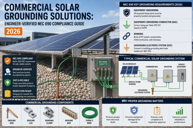
Commercial solar grounding solutions differ from residential in scale, complexity, and NEC compliance requirements. A rooftop residential system uses a single ground rod and 6 AWG copper. A commercial PV array — whether a ground-mount field, a carport structure, or a warehouse rooftop — requires an engineered grounding electrode system, equipotential bonding across hundreds of panel frames, and conductor sizing based on 3-phase OCPD ratings rather than residential branch circuits.
| Component | Residential | Commercial |
| EGC Wire Size | 10–12 AWG | 8–4 AWG (3-phase) |
| Grounding Electrode | Single 8ft rod | Multiple rods or ground grid |
| Bonding Method | Individual lugs | UL 2703 listed racking |
| OCPD Reference | NEC 250.122 | NEC 250.122 + 690.43 |
| Combiner Box | Optional | Required (large arrays) |
Introduction
Commercial solar installations carry significantly higher fault current potential than residential systems. Furthermore, they involve longer conductor runs, 3-phase inverter configurations, and structural grounding requirements that do not apply at the residential scale. Getting the grounding solution right on a commercial project protects the equipment, satisfies the Authority Having Jurisdiction (AHJ), and prevents costly rework after the inspection visit.
In my decade of reviewing commercial PV plan sets and field installations, grounding failures appear in two patterns:
- Installers apply residential grounding logic to a commercial-scale array and undersize both the Equipment Grounding Conductor (EGC) and the grounding electrode system.
- They miss the equipotential bonding requirement across large racking structures where rail sections connect mechanically but not electrically.
This guide addresses both patterns with the specific NEC references and hardware decisions that apply at commercial scale.
Why Commercial Solar Grounding Requires a Different Approach
Voltage and Scale Differences
A residential system typically operates as a single string or a few strings feeding one inverter at under 600V DC. A commercial system, by contrast, may combine dozens of strings through a combiner box, feeding a central or string inverter operating at 1000–1500V DC. Consequently, fault current potential is substantially higher. The grounding path must handle proportionally more energy before an overcurrent protection device (OCPD) clears the fault.
Overcoming Large Footprints
Moreover, commercial arrays often span large physical distances. Examples include a carport array covering a 200-space parking lot or a ground-mount field covering several acres. Therefore, the grounding electrode system must maintain equipotential across the entire structure, not just at the inverter connection point.
Navigating Dual Codes
NEC Article 690 governs PV-specific grounding requirements. Additionally, NEC Article 250 covers general grounding and bonding rules that apply to any electrical installation. For commercial systems, engineers must read both articles together alongside the inverter manufacturer’s specifications. Some central inverters specify grounding requirements beyond the NEC minimum.
People Also Ask:
What makes commercial solar grounding different from residential? Commercial systems operate at higher voltages (up to 1500V DC), carry greater fault current, use 3-phase inverters, and span larger physical areas. As a result, they require larger EGC conductors, engineered grounding electrode systems, and equipotential bonding across extended racking structures.
EGC Sizing for 3-Phase Commercial Arrays
Sizing by OCPD, Not Ampacity
On residential systems, most installers use 10 or 12 AWG copper for the EGC. However, on commercial 3-phase installations, the EGC size steps up significantly based on the OCPD rating per NEC Table 250.122.
- For a commercial string inverter with a 100A OCPD at the DC combiner, the minimum EGC size is 8 AWG copper.
- For a central inverter installation with a 200A OCPD, the minimum EGC steps up to 6 AWG.
- On larger utility-adjacent commercial systems with 400A or 600A OCPD ratings, you may need 3 AWG or larger.
Additionally, for 3-phase solar systems, the equipment grounding conductor runs must account for longer conductor paths. The minimum EGC gauge typically steps up to 10 AWG or 8 AWG copper on 3-phase commercial installations.
Avoid Common Conduit Violations
A critical mistake on commercial projects is sizing the EGC based on the conductor ampacity rather than the OCPD rating. NEC 250.122 is explicit: the OCPD protecting the circuit determines the EGC size, not the wire ampacity. Running the EGC separate from the PV source conductors also violates NEC 690.43 directly. Installers must run both inside the same conduit or cable assembly.
Grounding Electrode Systems for Commercial PV
Moving Beyond the Single Ground Rod
A single 8-foot ground rod is sufficient for most residential installations. For commercial PV, however, a single rod rarely satisfies the 25-ohm threshold required by NEC 250.56, particularly across the large footprint of a commercial ground-mount or carport array.
Commercial grounding electrode solutions fall into three main categories depending on site conditions.
1. Multiple Ground Rods
This is the most common commercial solution. Installers drive rods at a minimum of 6 feet apart and bond them together with a continuous 6 AWG or larger bare copper conductor. Each rod must achieve less than 25 ohms individually. Alternatively, you must bond two or more rods together — NEC 250.56 requires this automatically when a single rod cannot achieve the 25-ohm threshold.
2. Grounding Grids
On large ground-mount commercial arrays, an engineered grounding grid buried below the frost line provides the most reliable long-term electrode system. In areas with high soil resistivity, engineers specify interconnected grounding grids or chemical grounding enhancements to ensure a low-resistance connection to the earth. Grid conductors are typically 4/0 AWG bare copper, laid in a mesh pattern under the array footprint. Installers bond this mesh to the racking structure at multiple points.
3. Chemical Grounding Rods
In rocky or extremely dry soil where conventional rods cannot reach adequate depth, chemical grounding rods use a conductive compound. This compound expands into the surrounding soil over time. These rods are particularly useful in desert commercial installations where conventional rods achieve high resistance due to low moisture content.
Eliminating Ground Loops
For all commercial installations, the solar grounding electrode system must bond to the building’s or facility’s existing Grounding Electrode System (GES) per NEC 690.47. Failure to bond creates two separate ground reference points. This creates a ground loop that can route fault current into sensitive equipment rather than safely to earth.
People Also Ask:
How many ground rods does a commercial solar system need? Most commercial installations require a minimum of two rods spaced at least 6 feet apart and bonded together. Larger arrays with extended racking structures often need additional rods or a buried grounding grid to maintain equipotential bonding across the full array footprint and meet the NEC 250.56 threshold of 25 ohms or less.
UL 2703 Listed Racking: The Commercial Standard for Bonding
Why Integrated Racking Wins
At residential scale, some installers still use individual grounding lugs at each panel frame. At commercial scale, this approach is impractical and non-compliant. Instead, the commercial solar industry has standardized on UL 2703 listed racking systems that integrate bonding continuity across the entire array.
Many modern metallic PV racking systems carry UL 2703 listings specifically for supporting and bonding PV modules. These systems eliminate the outdated practice of drilling holes in module frames and connecting separate bonding wires. When using a UL 2703 listed system, you only need to run a single EGC from the array back to the inverter grounding busbar. The racking itself provides the bonding continuity across all panel frames.
The Danger of Unbonded Splices
However, the UL 2703 listing only applies when you install the racking exactly per the manufacturer’s instructions. On large commercial arrays, unbonded rail splice points represent the most common installation failure. When two rail sections connect mechanically without an approved splice bond, the EGC path breaks at that joint.
The array may look continuous from a distance, but the grounding path is discontinuous. A standard continuity test or visual inspection will not catch this unless the inspector probes across each individual splice.
[PV Module] —> [UL 2703 Rail Section 1] —> [UNBONDED SPLICE (PATH BREAKS)] —> [Rail Section 2]
Verification and Alternatives
For commercial arrays where UL 2703 listed racking is not available, WEEB washers provide an alternative bonding method at each panel-to-rail connection. Each WEEB must penetrate the anodized coating on both the panel frame and the rail to establish a valid ground path. On a 500-panel commercial array, this means verifying 500 individual connections — a massive labor investment. You can verify any racking system’s status through theUL Product iQ Database before specifying it.
Combiner Box Grounding in Commercial Arrays
Enclosure Bonding Rules
Most commercial PV installations use DC combiner boxes to aggregate multiple strings before feeding the inverter. The combiner box itself is a grounding checkpoint that installers frequently miss.
Every metal enclosure on the combiner box — including the box body, the door, and any internal subpanels — must bond to the EGC path per NEC 690.43. Furthermore, the EGC conductors from each string must terminate to a dedicated grounding busbar inside the combiner, not simply land on the enclosure chassis without a listed termination.
Terminal Lug Coordination
Large utility-scale combiners may require 2/0 or 4/0 AWG output conductors. Engineers must verify that the terminal lug conductor range matches the selected wire size to ensure a proper compression connection. Undersized lugs on a heavy-gauge EGC create a high-resistance termination that passes visual inspection but fails under fault conditions.
Preventing Multi-Box Interference
On commercial installations with multiple combiner boxes spread across an array field, each combiner’s grounding busbar must connect back to a common grounding point at the inverter. Running separate, isolated ground paths from each combiner back to different points on the main service panel creates multiple bonding paths. This forms a ground loop that can interfere with the inverter’s ground fault detection.
People Also Ask:
Does a commercial solar combiner box need a separate ground? No — and a separate, isolated ground causes compliance problems. The combiner box grounding busbar must connect back to the same grounding point as the inverter’s EGC termination. Multiple isolated ground points create ground loops that interfere with ground fault protection.
Equipotential Bonding for Carport and Ground-Mount Structures
Engineering a Safety Perimeter
Commercial carport solar installations and large ground-mount arrays present a unique grounding challenge: the structural steel or aluminum framework itself must achieve equipotential bonding across its entire length.
Equipotential bonding connects all metallic components within the PV system to the same electrical potential. This creates a safety perimeter that minimizes the potential voltage difference between different parts of the system during a fault. TheIEEE Standard 80 provides detailed guidance on equipotential grounding design for large electrical installations that commercial solar engineers reference alongside NEC 690.
Structural Requirements
For a carport array spanning 200 parking spaces, the structural columns, beams, and purlins must all bond together and connect to the grounding electrode system at multiple points. Installers cannot just ground one end of the structure. NEC 250.104 governs bonding of structural metal. For PV structures, this rule combines with NEC 690.43 to require that every metal component at risk of becoming energized connects to the EGC path.
In practice, commercial carport grounding uses a combination of UL 2703 listed racking for the panel bonding and a separate bare copper bonding conductor run the length of the structural steel. Installers connect this bonding conductor to the racking EGC at regular intervals. The bonding conductor connects to grounding rods at both ends of the structure and at intermediate points for structures exceeding 100 feet in length.
Transformer-Based vs Transformerless Central Inverters
The DC Grounding Divide
The distinction between transformer-based and transformerless inverters determines DC grounding requirements under NEC 690.41. The stakes are much higher on a commercial project because the wrong DC grounding approach on a large central inverter can damage equipment across the entire array.
- Central Inverters (Transformer-Based): These require DC system grounding. The DC negative bonds to earth through the Grounding Electrode Conductor (GEC). These units are common in older utility-adjacent commercial installations.
- String Inverters (Transformerless): NEC 690.41(B) prohibits DC system grounding at the DC level for these units. The inverter uses internal Ground Fault Protection (GFP) circuitry to detect faults. On a commercial installation with twelve transformerless string inverters, adding a DC system ground to any one of them can destabilize the GFP across all twelve units on the same array.
Transformer-Based Inverter —> Requires Solid DC Negative-to-Earth Bond
Transformerless Inverter —> Prohibits DC Grounding (Uses Internal GFP Circuitry)
Functional Ground Reference
Many modern commercial systems use an ungrounded PV array with a transformerless inverter. The PV array conductors do not solidly connect to earth. Instead, the inverter provides a functional ground reference and ground-fault monitoring. Equipment grounding of all metal parts remains fully required in both configurations — only the DC circuit grounding changes. For the most current inverter listing requirements, theUL 1741 Standard governs all grid-connected PV inverters.
People Also Ask:
Can a commercial solar system use both transformer-based and transformerless inverters? Technically yes, but each inverter type must follow its own NEC 690.41 requirement independently. Mixed configurations require careful design to ensure the two grounding approaches do not create a shared DC ground path, which would violate NEC 690.41(B) for the transformerless units.
Surge Protection Devices (SPDs) at Commercial Scale
Mitigating Atmospheric Exposure
Commercial arrays face substantially higher lightning exposure than residential installations due to their larger footprint and elevated profile in open terrain.
On commercial systems, Type 1 SPDs at each combiner box and Type 2 SPDs at the inverter AC output represent the standard configuration. Type 1 SPDs handle direct lightning attachment.NFPA 780 standards mandate them at the first point of entry in high-exposure installations. Type 2 SPDs handle induced surges and transient overvoltages from nearby strikes.
Lightning Protection Systems
For large ground-mount arrays in high-lightning-frequency regions, NFPA 780 lightning protection — separate from NEC grounding — may also apply. This includes air terminals (lightning rods) distributed across the array, a down conductor system, and bonding to the facility grounding electrode system.
The NREL Lightning Protection Guide for PV Systems serves as the authoritative field reference for commercial installers. While the NEC does not require NFPA 780 compliance for PV systems, the AHJ or the facility’s insurance carrier may impose this requirement before energization.
Common Commercial Grounding Mistakes
These are the issues commercial solar inspectors flag most consistently on large-scale projects:
- Undersized EGC for OCPD Rating: Applying residential EGC sizing logic to a commercial 3-phase system. The EGC must size per NEC Table 250.122 based on the OCPD, not the conductor ampacity.
- Unbonded Rail Splice Joints: Rail sections that connect mechanically but lack an approved electrical bond across the splice. This breaks the EGC path without any visual indication.
- Chassis Used as EGC Termination: Grounding conductors landed on the combiner box enclosure body rather than a listed grounding busbar inside. The chassis connection lacks the listing required for a valid EGC termination.
- Isolated Solar Ground Rod: Installing a ground rod for the solar array without bonding it to the facility’s existing GES. This creates two separate ground potentials, forming a ground loop that attracts fault current into electronics.
- Mixed DC Grounding on Multi-Inverter Arrays: Adding a DC system ground to one or more transformerless string inverters in a multi-inverter installation. This creates a prohibited DC ground path across the full array.
- Insufficient Grounding Electrode System: Using a single rod in high-resistivity soil on a large array footprint. Multiple rods or a buried grounding grid are required to achieve the 25-ohm threshold across the full structure.
- Omitted SPDs on Combiner Boxes: Residential-trained installers sometimes leave Type 1 SPDs off combiner boxes on commercial ground-mount arrays, leaving the inverter exposed to direct lightning attachment.
Maintenance and Annual Testing at Commercial Scale
Testing Protocols and Intervals
Commercial solar grounding systems require a more rigorous testing protocol than residential installations. Annual testing is the minimum standard. Quarterly testing is recommended for large utility-adjacent systems where a grounding failure affects substantial generation capacity.
Ground Resistance Testing
Use a fall-of-potential tester or a clamp-on ground resistance meter at each rod and at each racking section termination. TheIEEE Standard 81 fall-of-potential method is the industry standard for commercial ground resistance measurement. The 25-ohm threshold applies to each electrode independently. On a grounding grid system, resistance should measure well below 5 ohms across the full grid. Any reading above 10 ohms on a commercial installation warrants immediate investigation and remediation.
Bonding Continuity and SPD Checks
On large arrays with UL 2703 listed racking, perform a low-resistance ohmmeter test across each rail splice at least annually. Target readings should be under 0.1 ohm across any splice joint. Readings above 0.5 ohm indicate oxidation or mechanical loosening that compromises the EGC path.
Additionally, inspect each SPD for its status indicator and replace any unit showing a failed condition. SPDs are sacrificial devices that degrade with each surge event. On commercial installations in high-lightning areas, SPD replacement every 3–5 years is standard maintenance practice.
Record Keeping
Maintain a grounding test log for each commercial installation. AHJ reinspections and insurance audits frequently request grounding resistance records. While monitoring platforms from SolarEdge, Fronius, and Sungrow provide continuous ground fault alerts, these alerts confirm fault detection, not grounding continuity. Physical testing remains the only way to verify the hardware is sound.
People Also Ask:
How often should commercial solar grounding be tested? Annual testing is the minimum NEC-aligned standard. Large commercial and utility-adjacent systems benefit from quarterly testing, particularly after significant weather events. Each test should verify ground rod resistance below 25 ohms, bonding continuity across all rail splice points below 0.1 ohm, and active SPD status indicators.
Use-Case Recommendations
| Scenario | Recommended Solution |
| Rooftop Commercial (Warehouse) | UL 2703 listed racking, 8 AWG EGC minimum, two bonded ground rods at building GES connection |
| Ground-Mount Field (1–5 Acres) | Buried copper grounding grid, multiple rods at perimeter, Type 1 SPD at each combiner |
| Carport Array (50+ Spaces) | Structural steel equipotential bonding conductor full length, rods at both ends and mid-span |
| High-Resistivity Soil (Desert) | Chemical grounding rods, two-point resistance test before close, grid configuration preferred |
| Multi-Inverter (12+ String Inverters) | Single shared grounding busbar at inverter station, no isolated DC ground paths on any unit |
| High-Lightning Region | NFPA 780 assessment before design, Type 1 SPDs at all combiners, Type 2 at main AC output |
Conclusion
A commercial solar grounding solution is not a scaled-up version of a residential installation — it is an engineered system designed around higher fault current, longer conductor runs, 3-phase inverter configurations, and large structural footprints that must achieve equipotential bonding across their full extent.
The specific decisions that matter: EGC sizing per OCPD rating under NEC Table 250.122, UL 2703 listed racking for bonding continuity at scale, multiple ground rods or a buried grid to achieve the 25-ohm threshold, and proper combiner box EGC termination at a listed busbar rather than the chassis. Get these right, and the inspection passes on the first visit. Miss any one of them, and rework on a commercial array is measured in days of labor, not hours.
Annual resistance testing and bonding continuity checks protect a commercial asset that typically represents $200,000 to $2,000,000 in installed equipment. The testing takes four hours. The alternative is a ground fault that the protection system cannot clear because the grounding path it depends on was never sound.
Frequently Asked Questions
What Is a Commercial Solar Grounding Solution?
A commercial solar grounding solution is an engineered combination of equipment grounding conductors, grounding electrode systems, UL 2703 listed racking, combiner box bonding, and surge protective devices sized for large-scale PV installations operating at higher voltages and fault current levels than residential systems.
How Do You Ground a Large Commercial Solar Array?
Bond all panel frames and racking using UL 2703 listed racking or WEEB washers, run a correctly sized EGC based on NEC Table 250.122 OCPD rating to the inverter busbar, install multiple ground rods or a buried grid to achieve under 25 ohms, and bond everything to the facility’s existing GES per NEC 690.47.
What Size Ground Wire for a Commercial Solar System?
EGC size depends on the OCPD rating per NEC Table 250.122. A 100A OCPD requires 8 AWG minimum; a 200A OCPD requires 6 AWG minimum; a 400A OCPD requires 3 AWG minimum. Never size the EGC based on conductor ampacity alone.
Do Commercial Solar Panels Need a Grounding Grid?
Not always, but large ground-mount arrays in high-resistivity soil typically require a buried copper grounding grid to achieve the 25-ohm NEC threshold across the full array footprint. Multiple rods bonded together suffice for smaller commercial rooftop and carport installations.
What Is Equipotential Bonding in Commercial Solar?
Equipotential bonding connects all metallic components of a large PV structure — including racking, structural steel, carport columns, and enclosures — to the same electrical potential. This prevents voltage differences across the structure during a fault that could otherwise route current through personnel or sensitive electronics.
How Often Should Commercial Solar Grounding Be Tested?
Annual testing is the standard minimum. Quarterly testing is recommended for large or utility-adjacent systems. Each test should verify ground rod resistance below 25 ohms, rail splice bonding below 0.1 ohm, and SPD status indicators showing active condition.
What SPD Is Required for Commercial Solar?
Type 1 SPDs at each DC combiner box and Type 2 SPDs at the inverter AC output are the standard commercial configuration. In high-lightning regions, NFPA 780 lightning protection assessment is also recommended before system design is finalized.
Can I Use the Same Ground Rod for Solar and the Building?
The solar grounding electrode must bond to the building’s existing Grounding Electrode System per NEC 690.47, but commercial arrays typically require their own additional electrodes. Using only the building’s existing ground rod without supplemental electrodes rarely achieves the 25-ohm threshold required for a large array.

I am Ethan Brooks is an author dedicated to exploring sustainability, technology, and forward-thinking solutions. His writing highlights simple yet powerful ways to improve everyday life while protecting the planet. He believes knowledge can drive meaningful change. Discover more at ecopowersence.com.